
Table of Contents
Introduction
With the rapid advancement of technology, security solutions have become increasingly smart and efficient. One such solution is using RFID technology integrated with an Arduino to create a secure door lock system.
This guide will walk you through building your own RFID door lock system with Arduino, offering a practical and cost-effective way to enhance your security setup.
Understanding RFID Technology
RFID (Radio Frequency Identification) is a technology that uses electromagnetic fields to automatically identify and track tags attached to objects. It consists of three core components:
- RFID tag
- RFID reader
- Antenna
There are two main types of RFID systems:
- Active RFID: Powered by a battery and can transmit signals autonomously.
- Passive RFID: Powered by the electromagnetic energy transmitted from an RFID reader.
For building a DIY door lock system, a passive RFID system is usually preferred for its simplicity and cost-effectiveness.
For more technical details, you can refer to this Introduction to RFID technology.
Why Use Arduino for RFID Door Locks?
Arduino is one of the most popular microcontrollers for DIY electronics projects. Here’s why it’s ideal for this project:
- Ease of Use: Even beginners can quickly learn how to program and configure an Arduino.
- Flexibility: Arduino allows for easy integration with sensors, RFID modules, and actuators.
- Large Community Support: A massive community means plenty of tutorials, code samples, and troubleshooting tips are available.
If you need official documentation and references, visit the Arduino official documentation.
Components Required
To build an RFID door lock system using Arduino, you’ll need the following:
- Arduino Uno or any compatible microcontroller
- RFID reader module (MFRC522)
- RFID tags or cards
- Servo motor or an electronic lock
- Breadboard
- Jumper wires
- Power supply (battery or adapter)
Optional components for added features:
- LCD Display
- Buzzer
- LED indicators
Refer to the MFRC522 RFID module datasheet for detailed specifications of the RFID reader.
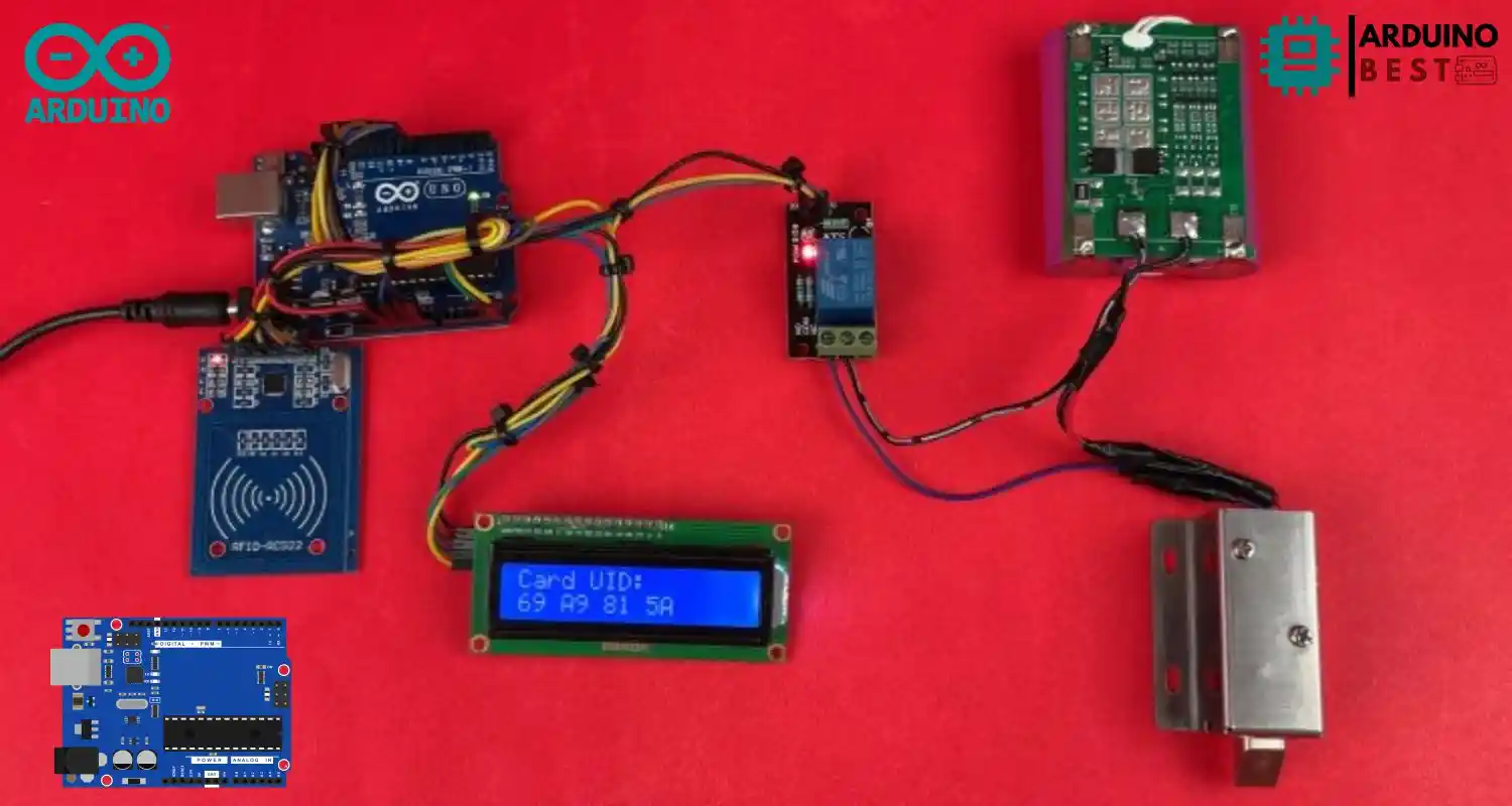
Circuit Diagram and Wiring
A reliable setup is crucial for the functionality of your project. Here’s how to wire it:
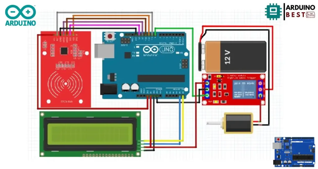
- Connect the RFID module’s pins (SDA, SCK, MOSI, MISO, GND, RST, 3.3V) to the respective pins on the Arduino.
- Connect the servo motor control wire to one of the PWM pins.
- Power the components appropriately using the Arduino’s 3.3V and 5V outputs.
- Use the breadboard to simplify connections and avoid loose wiring.
Tips:
- Always double-check connections before powering the system.
- Use a multimeter to verify voltage levels if something isn’t working.
Programming the Arduino
To program the Arduino, follow these steps:
- Install the Arduino IDE from the official website.
- Install the MFRC522 library by Miguel Balboa, available here.
Here’s a basic overview of the coding process:
- Initialize the RFID module and the servo motor.
- Continuously scan for RFID tags.
- If an authorized RFID tag is detected, activate the servo motor to unlock the door.
- Optionally, display messages on the LCD and activate the buzzer.
Make sure to properly comment your code for easier troubleshooting later.
Code Arduino
#include <MFRC522.h>
#include <LiquidCrystal_I2C.h>
// Define RC522 pins
#define RST_PIN 9
#define SS_PIN 10
// Relay pin
#define RELAY_PIN 8
// Initialize MFRC522 instance
MFRC522 rfid(SS_PIN, RST_PIN);
// Initialize LCD (address 0x27 may vary)
LiquidCrystal_I2C lcd(0x27, 16, 2);
// Authorized UID (replace with your tag's UID)
byte authorizedUID[] = {0x69, 0xA9, 0x81, 0x5A};
// Door status
bool doorLocked = true;
void setup() {
 // Initialize SPI and RC522
 SPI.begin();
 rfid.PCD_Init();
 // Initialize LCD
 lcd.init();
 lcd.backlight();
 // Set up relay pin
 pinMode(RELAY_PIN, OUTPUT);
 // Display startup message
 lcd.setCursor(0, 0);
 lcd.print("RFID Door Lock");
 delay(2000);
 lcd.clear();
 lockDoor(); // Start with door locked
}
void loop() {
 // Check if a new RFID card is present
 if (!rfid.PICC_IsNewCardPresent()) {
   return;
 }
 // Check if the RFID card can be read
 if (!rfid.PICC_ReadCardSerial()) {
   return;
 }
 // Display scanned UID
 lcd.clear();
 lcd.setCursor(0, 0);
 lcd.print("Scanning...");
 delay(2000);
 // Compare scanned UID with authorized UID
 if (isAuthorized(rfid.uid.uidByte, rfid.uid.size)) {
   lcd.setCursor(0, 1);
   lcd.print("Access Granted!");
   delay(2000);
   unlockDoor(); // Lock or unlock the door
 } else {
   lcd.setCursor(0, 1);
   lcd.print("Access Denied!");
   delay(2000);
   lockDoor();
 }
 // Halt communication with the card
 rfid.PICC_HaltA();
}
// Function to check if UID matches authorized UID
bool isAuthorized(byte *uid, byte size) {
 if (size != sizeof(authorizedUID)) {
   return false;
 }
 for (byte i = 0; i < size; i++) {
   if (uid[i] != authorizedUID[i]) {
     return false;
   }
 }
 return true;
}
// Function to lock the door
void lockDoor() {
 digitalWrite(RELAY_PIN, LOW); // Turn OFF relay (lock engaged)
 doorLocked = true;
 lcd.clear();
 lcd.setCursor(0, 0);
 lcd.print("Door Locked");
 delay(2000);
}
// Function to unlock the door
void unlockDoor() {
 digitalWrite(RELAY_PIN, HIGH); // Turn ON relay (unlock door)
 doorLocked = false;
 lcd.clear();
 lcd.setCursor(0, 0);
 lcd.print("Door Unlocked");
 delay(10000); // Keep door unlocked for 5 seconds
 lockDoor();  // Auto-lock after 5 seconds
}
Testing the System
After assembling and programming, testing is crucial:
- Power up the Arduino and all connected devices.
- Present the authorized RFID tag near the reader.
- Observe if the servo motor unlocks and locks the door properly.
- If it doesn’t work, verify the wiring, code, and power connections.
Common troubleshooting tips:
- Ensure correct orientation of RFID tags.
- Check library versions for compatibility.
- Verify code logic for handling tag IDs.
Enhancing the System
To make your project more user-friendly and professional, consider adding:
- LCD Display: Show messages like “Access Granted” or “Access Denied.”
- Buzzer: Audible alerts when a card is scanned or access is denied.
- LED Indicators: Different colors for access granted (green) or denied (red).
Advanced upgrades:
- Mobile app integration via Bluetooth or WiFi.
- Cloud-based access logging and control.
Security Considerations
Building a secure RFID door lock system goes beyond just hardware:
- Use unique and encrypted RFID tags.
- Regularly update the list of authorized tag IDs in your Arduino code.
- Protect the Arduino and RFID reader from tampering.
- Implement timeout features to prevent brute force attempts.
Physical security is just as important as digital security when it comes to access control.
Real-world Applications
An RFID door lock system has many real-world uses, including:
- Home automation: Secure and keyless entry for homes.
- Office access control: Monitor and control employee entry.
- Secure lockers: For gyms, libraries, and schools.
- Educational projects: Perfect for teaching IoT and embedded systems.
The versatility of Arduino makes it adaptable to various security setups.
Maintenance and Troubleshooting
To ensure long-term functionality:
- Conduct regular system tests.
- Replace worn-out RFID tags or faulty servo motors.
- Update firmware and code to fix vulnerabilities or improve efficiency.
- Check for loose wiring or physical damage.
Preventive maintenance will drastically extend the life of your DIY system.
FAQs
What is the range of an RFID reader?
Most passive RFID readers, like the MFRC522, have a range of about 2 to 5 centimeters.
Can multiple RFID tags be used with one system?
Yes, you can program your Arduino to recognize multiple authorized RFID tags.
How secure is an RFID door lock system?
While convenient, RFID security depends on the type of tags and system encryption used. Advanced encryption provides better security.
What happens if the Arduino loses power?
When power is lost, the system stops functioning. Using an uninterrupted power supply (UPS) or battery backup is recommended.
Can I integrate this system with other smart home devices?
Yes, you can expand your RFID door lock system to communicate with smart home hubs, apps, or even IoT cloud services.
Conclusion
Creating an RFID door lock system using Arduino is an exciting and rewarding project that combines security, electronics, and programming skills. It offers an affordable solution to upgrade security at home or the office.
With simple components and open-source resources, even beginners can build a professional-grade system. Once you are comfortable, you can enhance it further with mobile apps, cloud integration, and advanced security features.
Start building your system today and experience firsthand how RFID technology can revolutionize everyday security!