
Table of Contents
Introduction
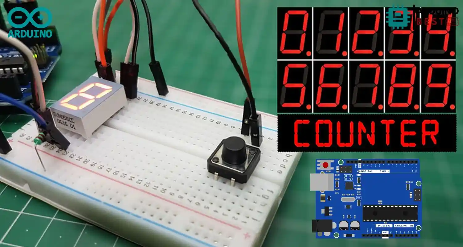
A seven segment display is a simple yet powerful way to show numbers on electronic devices. From digital clocks to calculators, seven segment displays are used almost everywhere. In this tutorial, we will learn how to create a counter using an Arduino and a push button, displayed on a seven segment display.
By the end of this guide, you’ll understand how to control a seven segment display with an Arduino Uno, how to increment or decrement numbers using buttons, and how to avoid common issues like button debouncing.
If you’re unfamiliar with digital input and output functions in Arduino, check out the Arduino Digital I/O Functions documentation to understand the basics.
Understanding Seven Segment Displays
A seven segment display consists of seven LEDs (labeled A through G) arranged in a figure-eight pattern. Each segment can be lit individually to display numbers from 0 to 9 and a few letters.
There are two main types of seven segment displays:
- Common Cathode: All the cathode (negative) terminals of the LEDs are connected together.
- Common Anode: All the anode (positive) terminals are connected together.
To learn more about the structure and working principles of a seven segment unit, refer to 7-Segment Display Basics.
Applications of seven segment displays include:
- Digital clocks
- Electronic meters
- Basic digital counters
Components Required
To build this project, you’ll need the following components:
- Arduino Uno board
- Single-digit seven segment display (common cathode recommended)
- Two push buttons
- 220Ω and 10kΩ resistors
- Breadboard
- Jumper wires
Optional components:
- Capacitor for hardware debouncing
- External power supply if not using USB
Circuit Diagram and Wiring
Setting up the circuit involves connecting each segment of the seven segment display to an Arduino pin through a resistor to limit the current. The push buttons will be connected with pull-down resistors to ensure stable readings.
Pin Configuration Example:
- A → Pin 2
- B → Pin 3
- C → Pin 4
- D → Pin 5
- E → Pin 6
- F → Pin 7
- G → Pin 8
Button Wiring:
- First push button: increment counter
- Second push button: decrement counter
The push buttons are wired using a pull-down resistor to keep the input LOW when the button is not pressed.
Writing the Arduino Code
Let’s break down the structure of the code you’ll upload to the Arduino Uno.
Code Arduino
const int a = 8;  //For displaying segment "a"
const int b = 9;  //For displaying segment "b"
const int c = 4;  //For displaying segment "c"
const int d = 5;  //For displaying segment "d"
const int e = 6;  //For displaying segment "e"
const int f = 2;  //For displaying segment "f"
const int g = 3;  //For displaying segment "g"

bool bPress = false;
const int buttonPin = 10;

// Variables will change:
int buttonPushCounter = 0;   // counter for the number of button presses
int buttonState = 0;         // current state of the button
int lastButtonState = 0;     // previous state of the button

void setup() {
  // put your setup code here, to run once:
  pinMode(a, OUTPUT);  //A
  pinMode(b, OUTPUT);  //B
  pinMode(c, OUTPUT);  //C
  pinMode(d, OUTPUT);  //D
  pinMode(e, OUTPUT);  //E
  pinMode(f, OUTPUT);  //F
  pinMode(g, OUTPUT);  //G

  pinMode( buttonPin , INPUT_PULLUP );
  Serial.begin(9600);
  displayDigit(buttonPushCounter);
}

void loop() {

   buttonState = digitalRead(buttonPin);

   // compare the buttonState to its previous state
  if (buttonState != lastButtonState) {
    // if the state has changed, increment the counter
    if (buttonState == LOW) {
      // if the current state is HIGH then the button went from off to on:
      bPress = true;
      buttonPushCounter++;
      if( buttonPushCounter > 9) buttonPushCounter =0 ;
      Serial.println("on");

    } else {
      // if the current state is LOW then the button went from on to off:
      Serial.println("off");
    }
    // Delay a little bit to avoid bouncing
    delay(50);
  }
  // save the current state as the last state, for next time through the loop
  lastButtonState = buttonState;

  if( bPress ){
     turnOff();
     displayDigit(buttonPushCounter);
  }


}


void displayDigit(int digit)
{
 //Conditions for displaying segment a
 if(digit!=1 && digit != 4)
 digitalWrite(a,HIGH);

 //Conditions for displaying segment b
 if(digit != 5 && digit != 6)
 digitalWrite(b,HIGH);

 //Conditions for displaying segment c
 if(digit !=2)
 digitalWrite(c,HIGH);

 //Conditions for displaying segment d
 if(digit != 1 && digit !=4 && digit !=7)
 digitalWrite(d,HIGH);

 //Conditions for displaying segment e
 if(digit == 2 || digit ==6 || digit == 8 || digit==0)
 digitalWrite(e,HIGH);

 //Conditions for displaying segment f
 if(digit != 1 && digit !=2 && digit!=3 && digit !=7)
 digitalWrite(f,HIGH);

 //Conditions for displaying segment g
 if (digit!=0 && digit!=1 && digit !=7)
 digitalWrite(g,HIGH);

}
void turnOff()
{
  digitalWrite(a,LOW);
  digitalWrite(b,LOW);
  digitalWrite(c,LOW);
  digitalWrite(d,LOW);
  digitalWrite(e,LOW);
  digitalWrite(f,LOW);
  digitalWrite(g,LOW);
}
Setup and Loop Functions
- Setup(): Define the pin modes for the seven segments and push buttons.
- Loop(): Continuously check for button presses and update the counter accordingly.
Defining Pins and Variables
Assign pins to each segment and create variables to track the counter value.
Implementing the Counter Logic
Use digitalRead() to detect button presses and modify the counter:
- Increment button adds 1
- Decrement button subtracts 1
Limit the counter between 0 and 9 to prevent undefined behavior.
Debouncing the Buttons
When a button is pressed, the signal can bounce, causing multiple counts. To solve this, implement a software debounce method, or refer to the Debounce Tutorial by Arduino for a ready-made solution.
Displaying Numbers
Manually turn on and off segments to display the correct number. For example:
- 0 → segments A, B, C, D, E, F
- 1 → segments B, C
You can also simplify coding by using the SevSeg Library on GitHub.
Enhancing the Project
Once the basic counter is working, you can enhance it further:
- Add multiple digits by using multiplexing techniques.
- Use libraries like SevSeg to manage complex displays more efficiently.
- Add extra features:
- Reset button to reset counter to 0
- Auto-increment or auto-decrement features after long button presses
- Adjust brightness with Pulse Width Modulation (PWM)
Troubleshooting Common Issues
Here are some common issues you might face:
- Display not working: Double-check wiring connections and resistor values.
- Incorrect numbers displayed: Verify the segment-to-pin mapping.
- Button presses not registering: Improve debouncing either via software or hardware capacitors.
FAQs
How do I determine if my seven segment display is common cathode or anode?
Use a multimeter. Check the common pin: if connecting positive voltage lights segments, it’s common cathode; if negative voltage lights them, it’s common anode.
Can I use a single push button for both increment and decrement?
Yes, you can program the button to:
- Short press → increment
- Long press → decrement
How can I prevent the counter from exceeding its limits?
In your code, add conditions:
if (counter > 9) counter = 9;
if (counter < 0) counter = 0;
Is it possible to display letters on a seven segment display?
Some letters like A, b, C, d, E, F can be displayed, but full alphabet representation is limited.
How do I add a reset function to the counter?
Add a third push button and include code logic to reset the counter to zero when pressed.
Conclusion
Building an Arduino seven segment display counter with a push button is a great beginner project to master basic digital electronics and embedded systems. By understanding wiring, coding logic, and debouncing, you set the foundation for more complex projects like multi-digit counters and timers.
Experiment with enhancements, libraries, and different types of displays to keep challenging yourself!